Press ![]() [EXIT]
[EXIT]
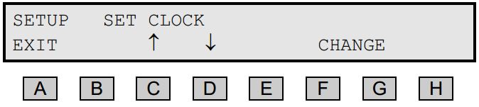
Press ![]() [SETUP]
[SETUP]
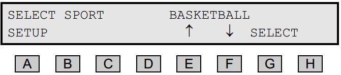
Press ![]() or
or ![]()
![]() until the menu SET CLOCK appears
until the menu SET CLOCK appears
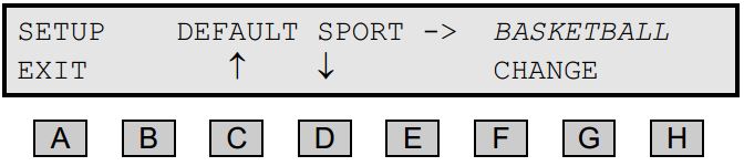
Press ![]() [CHANGE]
[CHANGE]
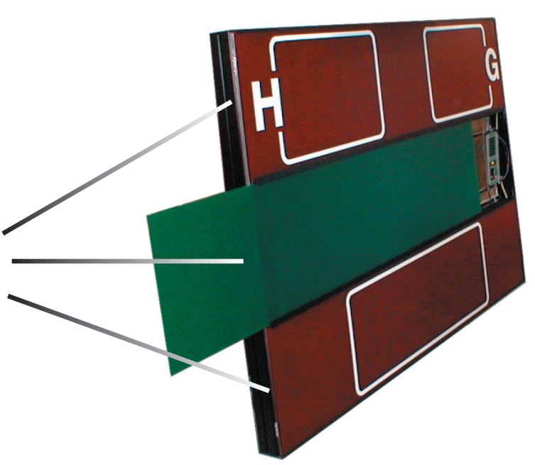
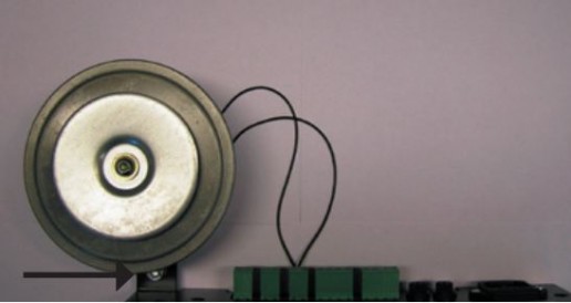
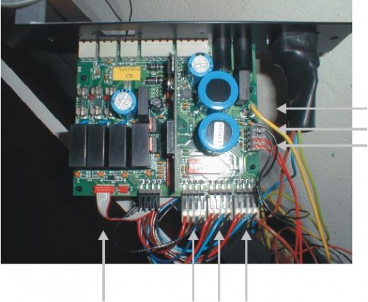
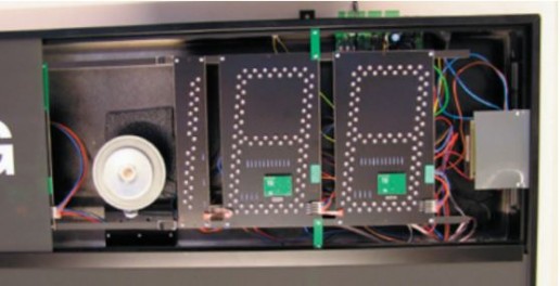
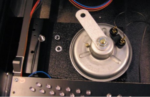
Horn mounted inside the scoreboard
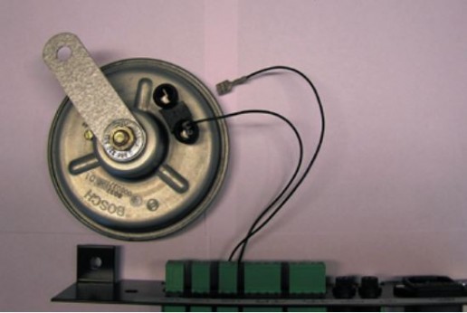
Horn mounted outside the scoreboard
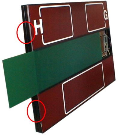
Horn mounted inside the scoreboard
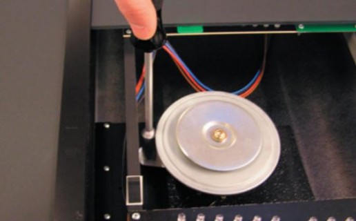
Horn mounted outside the scoreboard